OAUSA Net - August 29 Ham Radio Towers
Posted: Thu Aug 29, 2013 8:24 am
Product Review - Custom switch panel from GaugePlates.com
It seems that with newer vehicles (and some 70's Swiss troop transports as well ) there is never enough room for all of the auxiliary system switches and indicators you would like. A solution I found on the Internet are custom gauge and switch panels. The one shown is from -
http://www.gaugeplates.com
This company can make all kinds of custom gauge and switch panels. These panels are very professional looking and well made with backlit labels giving a very factory look. If you have a spot on the dash or elsewhere they can make a panel to fit.
The panel shown here is for my '04 Tacoma. It goes in the spot for the stock radio. I'm running a Yaesu FTM-10R 2m/440 radio which include AM, FM stereo, and aux input so the stock radio is redundant. The head unit for the FTM-10R is mounted on a RAM mount arm which is held securely in place by one of the right front seat bolts.
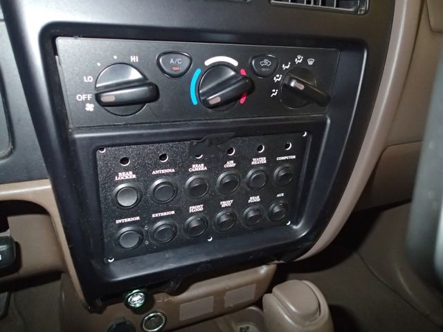
The picture below shows the panel temporally held in place in the Tacoma. The holes at the top will eventually hold RGB LEDs. The plan is to use varying color of the LEDs to give the status for the top row of systems. Various sensors and signals will be monitored by using an Arduino prototyping board (http://www.arduino.cc). Development of the Arduino based monitoring system could be the topic of a future net.
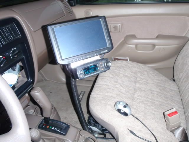
A picture of the dash with the radio removed. The FTM-10R and PC touch screen are on the RAM mount.
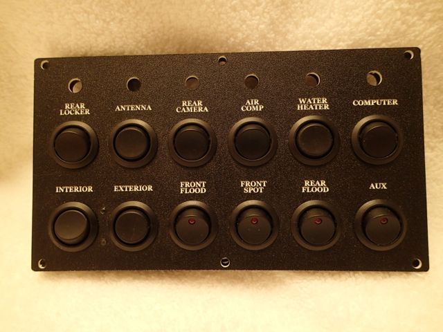
Here is a picture of the panel with the mounted switches. GaugePlates offers a wide variety of switches, indicator lights, and gauge hole options.
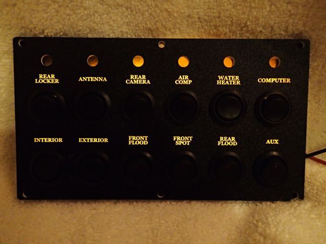
Here is the panel with the labels illuminated. The color balance is a little off in this picture. The labels are actually an amber color which is very close to the backlighting of the OEM controls in the Tacoma.
Main Topic - Ham Radio Towers
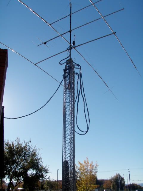
Here is a picture of a 3 section crank up tower. Collapsed the tower is 22 feet high. The antenna mast adds another 12 feet to that. The tower is 60 feet high when completely raised. The antenna rotator is mounted inside the top segment of the tower. There is thrust bearing at the top of the tower assembly which bears the weight of the mast and antennas. The only load on the rotator is from turning the mast and antenna stack.
Note the arms which hold the cables away from the tower. They keep the cables up and out of the way as the tower is raised and lowered.
The tower is mounted on a concrete base that measures 4' x 4' x 8' deep. The concrete is reinforced with a rebar cage built to the tower manufacturer's specifications. The tower itself is supported by 3 large "L" shaped bolts which are cast into the concrete. The bolts were held in place by a jig during the concrete pour. The specifications for the tower foundation required a continuous pour of concrete. To speed up the process a concrete pump was used to deliver the concrete from the mixer truck parked in front of the house on the street to the foundation location in the back yard. As it was, there were 6 people on site to work the vibrator which made sure there were no air pockets in the pour, make sure the forms and jig remained in place, and to finish the concrete after the pour. The hole for the foundation was slightly larger than was required. It was a good thing that extra concrete was ordered as concrete pump started sucking air just as the last bit went into the form. There was quite a bit of concrete that could have been recovered from the pumping equipment and hose if necessary but it would have been alot of work.
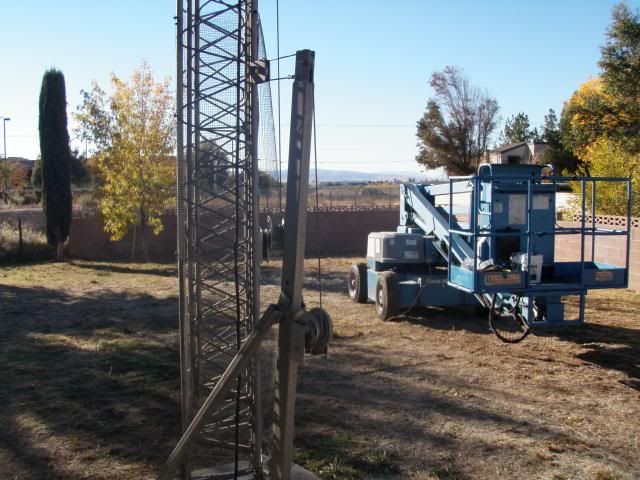
Here is the lower part of the tower with the raising jig attached. The rasing jig allows the tower to pivot on two bolts in the tower base. The tower is attached to the base laying down. The winch and cable on the raising fixture are used to raise the tower to a vertical position. The raising fixture was left on the tower with the notion that the tower could be lowered for antenna maintenance. It turned out that it was easier and safer to use a lift for this purpose since the large HF antenna prevents the mast from being lowered all the way.
Look carefully and you can see wire mesh around the lower portion of the tower. This was put in pace to prevent anyone from attempting to climb the tower like a ladder. A ham radio tower can be considered an "attractive nuisance" so preventative measures need to be taken to prevent anyone, espcially curious childern, from injuring themselves. The mesh was tightened around the tower as part of the last maintenance day. It is also common to attach metal plates to the lower section of the tower to prevent climbing.
Here is some information on the attractive nisiance doctrine - http://en.wikipedia.org/wiki/Attractive ... e_doctrine
The potential legal exposure of being an attractive nusiance and with appartments next door reinforce the the need for obtaining proper building permits for any tower project.
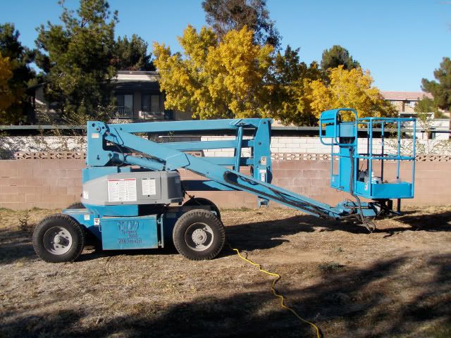
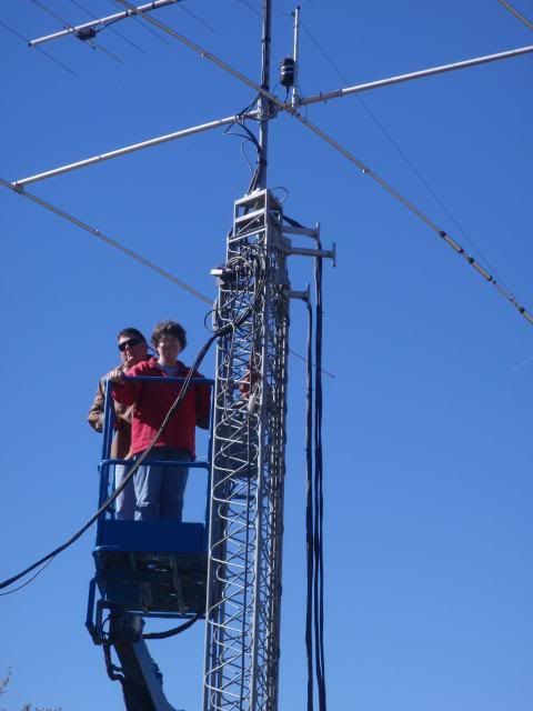
Here is an important peice of equipment for proper tower maintenance. Proper use of the lift does not require much training althgouth a good dose of common sense helps keep your operation safe. You need to plan your moves and a backout procedure before getting in close to tower to avoid accidents or damage to the antennas.
You will be working very high up in the air even with the tower lowered. The top of the mast is approximately 34 feet high with the tower lowered.
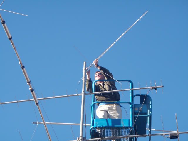
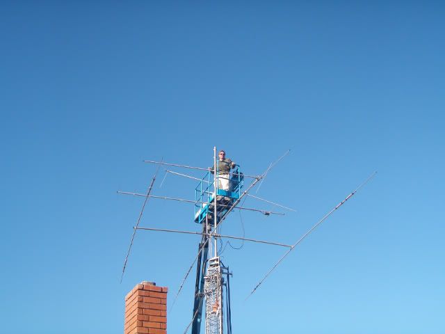
The lift makes it easy and safe to work at the very top of the tower. Here an omni directional 2m/440 antenna is being installed on top of the antenna mast. A safety belt was supplied with rental of the lift and it was used.
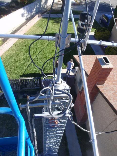
This is a view looking down on top of the tower. You can see the thrust bearing that carries the weight of the mast and antenna stack. You can also see the arms that hold the antenna cables. Pleanty of slack is necessary at the top to allow the antenna mast to rotate. There is a stop in the rotator preventing it from turning more than one full revolution.
Happiness is a safely completed tower project with no injuries or trips to the emergency room.
It seems that with newer vehicles (and some 70's Swiss troop transports as well
http://www.gaugeplates.com
This company can make all kinds of custom gauge and switch panels. These panels are very professional looking and well made with backlit labels giving a very factory look. If you have a spot on the dash or elsewhere they can make a panel to fit.
The panel shown here is for my '04 Tacoma. It goes in the spot for the stock radio. I'm running a Yaesu FTM-10R 2m/440 radio which include AM, FM stereo, and aux input so the stock radio is redundant. The head unit for the FTM-10R is mounted on a RAM mount arm which is held securely in place by one of the right front seat bolts.
The picture below shows the panel temporally held in place in the Tacoma. The holes at the top will eventually hold RGB LEDs. The plan is to use varying color of the LEDs to give the status for the top row of systems. Various sensors and signals will be monitored by using an Arduino prototyping board (http://www.arduino.cc). Development of the Arduino based monitoring system could be the topic of a future net.
A picture of the dash with the radio removed. The FTM-10R and PC touch screen are on the RAM mount.
Here is a picture of the panel with the mounted switches. GaugePlates offers a wide variety of switches, indicator lights, and gauge hole options.
Here is the panel with the labels illuminated. The color balance is a little off in this picture. The labels are actually an amber color which is very close to the backlighting of the OEM controls in the Tacoma.
Main Topic - Ham Radio Towers
Here is a picture of a 3 section crank up tower. Collapsed the tower is 22 feet high. The antenna mast adds another 12 feet to that. The tower is 60 feet high when completely raised. The antenna rotator is mounted inside the top segment of the tower. There is thrust bearing at the top of the tower assembly which bears the weight of the mast and antennas. The only load on the rotator is from turning the mast and antenna stack.
Note the arms which hold the cables away from the tower. They keep the cables up and out of the way as the tower is raised and lowered.
The tower is mounted on a concrete base that measures 4' x 4' x 8' deep. The concrete is reinforced with a rebar cage built to the tower manufacturer's specifications. The tower itself is supported by 3 large "L" shaped bolts which are cast into the concrete. The bolts were held in place by a jig during the concrete pour. The specifications for the tower foundation required a continuous pour of concrete. To speed up the process a concrete pump was used to deliver the concrete from the mixer truck parked in front of the house on the street to the foundation location in the back yard. As it was, there were 6 people on site to work the vibrator which made sure there were no air pockets in the pour, make sure the forms and jig remained in place, and to finish the concrete after the pour. The hole for the foundation was slightly larger than was required. It was a good thing that extra concrete was ordered as concrete pump started sucking air just as the last bit went into the form. There was quite a bit of concrete that could have been recovered from the pumping equipment and hose if necessary but it would have been alot of work.
Here is the lower part of the tower with the raising jig attached. The rasing jig allows the tower to pivot on two bolts in the tower base. The tower is attached to the base laying down. The winch and cable on the raising fixture are used to raise the tower to a vertical position. The raising fixture was left on the tower with the notion that the tower could be lowered for antenna maintenance. It turned out that it was easier and safer to use a lift for this purpose since the large HF antenna prevents the mast from being lowered all the way.
Look carefully and you can see wire mesh around the lower portion of the tower. This was put in pace to prevent anyone from attempting to climb the tower like a ladder. A ham radio tower can be considered an "attractive nuisance" so preventative measures need to be taken to prevent anyone, espcially curious childern, from injuring themselves. The mesh was tightened around the tower as part of the last maintenance day. It is also common to attach metal plates to the lower section of the tower to prevent climbing.
Here is some information on the attractive nisiance doctrine - http://en.wikipedia.org/wiki/Attractive ... e_doctrine
The potential legal exposure of being an attractive nusiance and with appartments next door reinforce the the need for obtaining proper building permits for any tower project.
Here is an important peice of equipment for proper tower maintenance. Proper use of the lift does not require much training althgouth a good dose of common sense helps keep your operation safe. You need to plan your moves and a backout procedure before getting in close to tower to avoid accidents or damage to the antennas.
You will be working very high up in the air even with the tower lowered. The top of the mast is approximately 34 feet high with the tower lowered.
The lift makes it easy and safe to work at the very top of the tower. Here an omni directional 2m/440 antenna is being installed on top of the antenna mast. A safety belt was supplied with rental of the lift and it was used.
This is a view looking down on top of the tower. You can see the thrust bearing that carries the weight of the mast and antenna stack. You can also see the arms that hold the antenna cables. Pleanty of slack is necessary at the top to allow the antenna mast to rotate. There is a stop in the rotator preventing it from turning more than one full revolution.
Happiness is a safely completed tower project with no injuries or trips to the emergency room.